Set model definition
Once you've created a model, the next step is to define its structure and how it will process data.
In Model Definition lays the groundwork for how the data is given to the model.
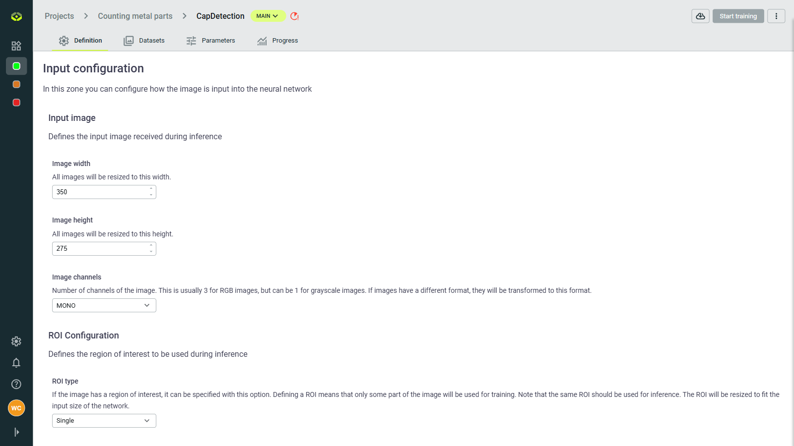
Input configuration
Define image dimensions and channels (RGB or grayscale).
Image size: Set width and height (e.g., 512×512 pixels)
Channels: Choose between RGB (3 channels) or Grayscale (1 channel) images.
RoI (Region of interest): Optionally specify a sub-area of images to focus training on relevant parts.
- Roi type: None, Single, dynamic
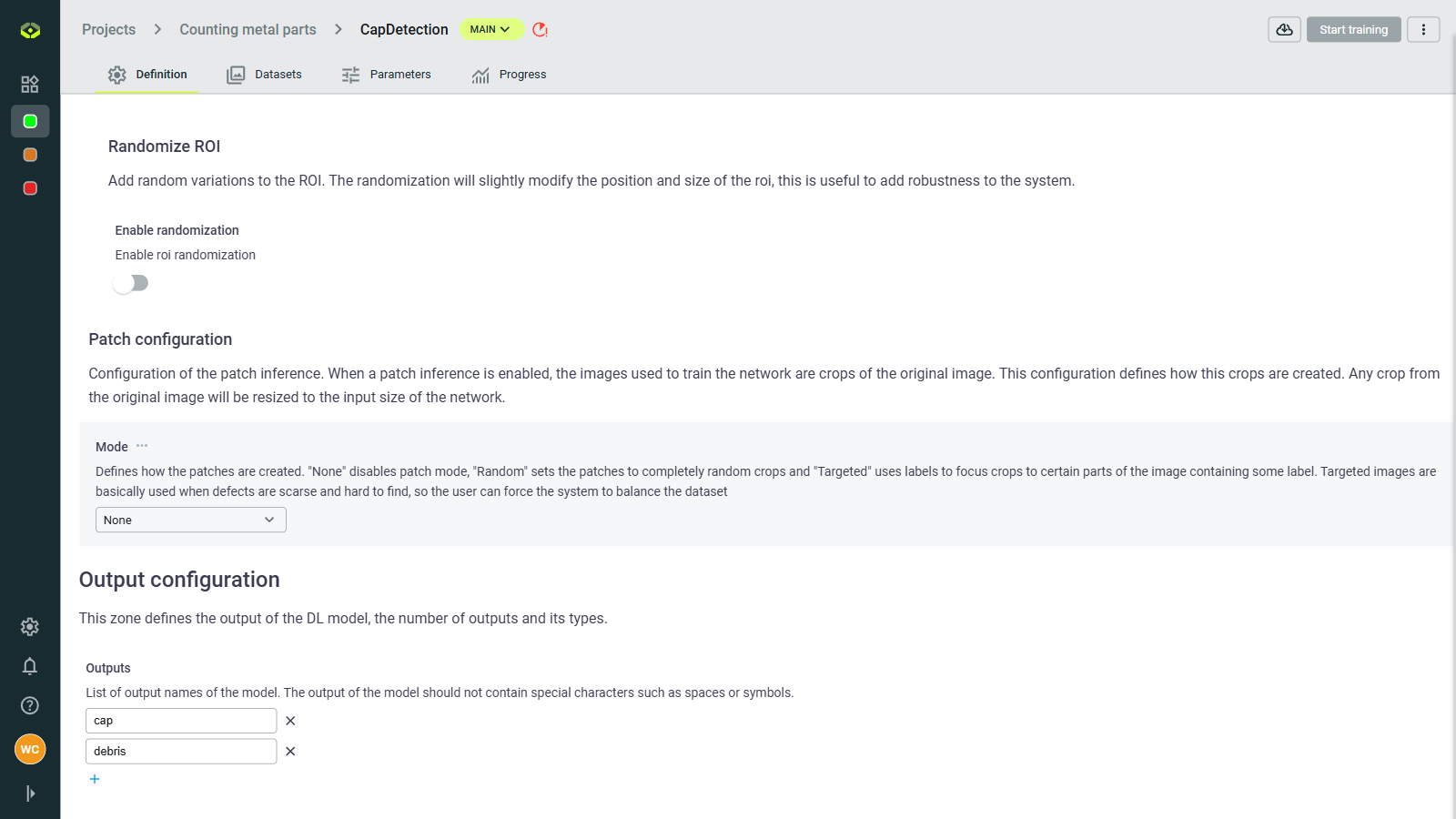
Patch mode: Split large images into smaller patches.
Images larger than 700 x 700 px may cause training errors. In this case, use Patch mode to divide images into smaller sub-images. It's highly recommended to apply an overlap when patching to avoid cutting important content.
Patch inference
For very large images (e.g., high-resolution scans, satellite imagery), patch mode divides them into smaller sections for processing:
- Patch size: Dimensions of each sub-image (e.g., 512×512 pixels)
- Overlap: How much patches should overlap (e.g., 25%)
- Higher overlap (30-50%) ensures objects aren't cut between patches
- Lower overlap (10-20%) reduces computation but may miss objects at boundaries
When to use patching:
- Images larger than 1000×1000 pixels
- High-resolution medical or industrial imagery
- Satellite or aerial photography
- When objects of interest are small relative to the full image
Recommended settings:
- For large objects: Larger patches (800×800) with 15-20% overlap
- For small objects: Smaller patches (512×512) with 30-50% overlap
Output configuration
This configuration ensures that your model receives well-prepared data and that outputs are clearly defined.
- Output Configuration: Define output names (special characters are not allowed) and structure your model's results.